Ахулл
Чт, 04 августа 2016 12:17
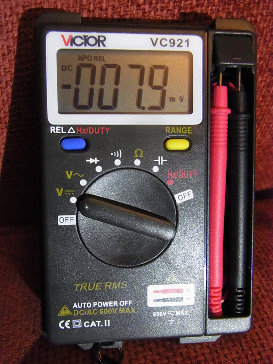
Обычно вещи, как правило, работают наоборот, мультиметр используется для того, чтобы ткнуть на плате STM32, однако после этот взлом, Показаны на несколько месяцев назад, я ткнул в 7 фунтов стерлингов.99 Victor VC921 True RMS Multymeter (Истинный RMS важен, так как существует несколько вариантов этого измерителя), чтобы обеспечить серийный выход и изменить его с измерителя 4000 до 8000 счисления.
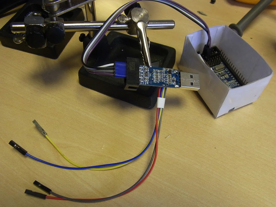
Я не фотографировал операцию, чтобы привлечь ИК -светодиод, резистор 100 Ом и пару проводов на печатную плату, но я сделал кучу других фотографий, которые вы можете найти здесь...
Вот эскиз, используемый для модификации 24C02 Eerom, чтобы переключить бит прошивки, чтобы включить сериал, и изменить байты, чтобы дать 6000 или 8000 счетов.
// --------------------------------------
// Modified i2c_scanner to find, dump and update a DTM0660 bassed multimeter EEROM
// to hack in missing features.
//
// See http://www.kerrywong.com/2016/03/19/hacking-dtm0660l-based-multimeters/comment-page-1/#comment-874169
// for more about hacking this chipset
//
// The i2c scanner code came with the following comments.
// Version 1
//    This program (or code that looks like it)
//    can be found in many places.
//    For example on the Arduino.cc forum.
//    The original author is not know.
// Version 2, Juni 2012, Using Arduino 1.0.1
//     Adapted to be as simple as possible by Arduino.cc user Krodal
// Version 3, Feb 26  2013
//    V3 by louarnold
// Version 4, March 3, 2013, Using Arduino 1.0.3
//    by Arduino.cc user Krodal.
//    Changes by louarnold removed.
//    Scanning addresses changed from 0...127 to 1...119,
//    according to the i2c scanner by Nick Gammon
//    http://www.gammon.com.au/forum/?id=10896
// Version 5, March 28, 2013
//    As version 4, but address scans now to 127.
//    A sensor seems to use address 120.
//
//
// This sketch tests the standard 7-bit addresses
// Devices with higher bit address will not be seen properly.
//
// Additional i2c hints from http://playground.arduino.cc/Code/I2CEEPROM
//

// This code was written for and teseted on and STM32F103C8T6 - the so called BluePill -  see http://wiki.stm32duino.com/index.php?title=Blue_Pill
// but should work pretty much unmodified on most 'duinos.

// Thanks to the many coding giants, who's shoulders this sketch stands upon.
//

// The hexdump of the 24c02 will appear on the STM32 USB serial device, or UART1, depending on the settings in the IDE.
// See http://stm32duino.com for details of how the serial ports on the STM32F103XX devices are defined.

// For most Multimeters, you should be able to use a SOC8 clamp  to connect without the inconvenience of soldering to the board.
// Search Ebay for "SOIC8 SOP8 Flash Chip IC Test Clips Socket Adpter BIOS" or similar.

#include

#define BLINK_PIN PC13   // Unused.. Can be used to assist with debugging.

#define BOARD_POWER PB9  // This can theoretically be used to power the multimeter/24c02 since the board draws a few miliamps.
// In the end, I just opted to power the board from 3v3 directly, as this makes manually resetting the multimeter only, easier.

#define BOARD_WP PB8     // Pull down WP pin to allow us to write to the 24c02 - by default this is held high by a pullup resistor on the multimeter.

void setup()
{
// Allow the USB to re-enumerate before we attempt to talk. You can probably shorten this delay considerably.
delay(30000);

// Using the BluePill, or other STM32F103XX boards, PB6 is SCL => Pin 6 on the 24C02
//                                                  PB7 is SDA => Pin 5 on the 24C02

//                                                  PB8 is GPOI used to pull WP (Write Protect) (Pin7) low on the 24C02 to allow writing to the chip.
//                                                  There is a pullup on WP on the Victor VC921 and probably most other devices, so we need to pull low to write.


// Power up the multimeter if connected to the BOARD_POWER
pinMode(BOARD_POWER, OUTPUT);
digitalWrite(BOARD_POWER, HIGH);

//Enable writing to the eerom
pinMode(BOARD_WP, OUTPUT);
digitalWrite(BOARD_WP, LOW);

Serial.println("\nDTM0660 EEROM dumper and updater.");

Wire.begin();
Serial.println("Waiting for DTM0660 POST and  i2c Bus to settle.");
delay(3000);
}


void loop()
{
byte error, address;
int nDevices;

Serial.println("Scanning...");

nDevices = 0;
for (address = 1; address < 127; address++ )
{
// The i2c_scanner uses the return value of
// the Write.endTransmisstion to see if
// a device did acknowledge to the address.
Wire.beginTransmission(address);
error = Wire.endTransmission();

if (error == 0)
{
Serial.print("\nI2C device found at address 0x");
if (address < 16) {
Serial.print("0");
}
Serial.print(address, HEX);
Serial.println(" ");

// Dump the current rom values, so we have somthing to fall back on if it all goes pear shaped.
// NOTE: The 24c02 also contains calibration values, so should be unique to the meter, simply pasting the hexdump from
//       one meter to another will screw up the calibration.

dump24c02(address);

// Enable serial.
// NOTE: On some meters, this will break the button matrix, or screw up some other features.
//       You do this entirely at your own risk.. magic smoke and a dead meter may result.
//       If in doubt, check whether pin 20 on the DTM0660 looks to be connected to some other circuitry before attempting to enable serial output.
//       It is however safe to do this on the version of Victor VC921 I havem as the Tx pin pad is not connected to anything else.

enableRS232();

//Select one of the followig three modes.

//enable4000Count();
//enable6000Count();
enable8000Count();

extendPowerOn();
nDevices++;
}
else if (error == 4)
{
Serial.print("Unknow error at address 0x");
if (address < 16)
Serial.print("0");
Serial.println(address, HEX);
}
}
if (nDevices == 0)
Serial.println("No I2C devices found\n");
else

Serial.println("\nDone.\n");

// Put any changes to bytes immediately after the dump, since that will ensure they hit the found i2c device.

delay(5000);           // Wait 5 seconds then re-scan.
}

void dump24c02(byte i2cAddress)
{
int addrPointer = 0;
int romLength = 0xff;    // 24c02 - 256x8 bits (256 bytes)
byte b = 0;


Serial.println("-- : 00 01 02 03 04 05 06 07 08 09 0A 0B 0C 0D 0E 0F");
while (addrPointer <= romLength)
{
if (!(addrPointer % 16)) {
Serial.print("\n");
if (addrPointer < 16) {
Serial.print("0");
}

Serial.print(addrPointer, HEX);
Serial.print(" : ");
}

b = i2c_eeprom_read_byte(i2cAddress, addrPointer);  // Read byte
addrPointer++;                                      // increment address pointer
if (b < 0x10) {
Serial.print("0");
}
Serial.print(b, HEX);                               // Print byte
Serial.print(" ");
}

Serial.println(" ");

}

byte i2c_eeprom_read_byte( int deviceaddress, unsigned int eeaddress ) {

Wire.beginTransmission(deviceaddress);

Wire.write((int)eeaddress);
Wire.endTransmission();
Wire.requestFrom(deviceaddress, 1);

if (Wire.available()) {
return Wire.read();
} else {
return 0xff;
}

}


void i2c_eeprom_write_byte( int deviceaddress, unsigned int eeaddress, byte data ) {
digitalWrite(BOARD_WP, LOW);
delay(100);
int rdata = data;
Wire.beginTransmission(deviceaddress);
Wire.write((int)(eeaddress)); //
Wire.write(rdata);
Wire.endTransmission();
//digitalWrite(BOARD_WP, HIGH);
}

void enableRS232() {
Serial.println("Enabling RS232");
i2c_eeprom_write_byte(0x50, 0xFA, 0xCE);
Serial.println("Done");
}

void extendPowerOn() {
Serial.println("Extending Power On time");
i2c_eeprom_write_byte(0x50, 0xFB, 0x1e);
Serial.println("Done");
}


void enable8000Count() {
Serial.println("Enabling 8000 Count Mode");
// Enable 8000 Count - Values taken from - this thread. May require a little polishing, but do appear to work.
// http://www.eevblog.com/forum/testgear/canadian-tire-mastercraft-dmm-new-and-old-revision-teardown/msg928377/#msg928377
i2c_eeprom_write_byte(0x50, 0x10,  0x40); // Full Scale 0x1F40 - 8000
i2c_eeprom_write_byte(0x50, 0x11,  0x1F); // Note: Little endian byte swap
//
i2c_eeprom_write_byte(0x50, 0x12,  0x41); // Range Up 0x1F41 - 8001
i2c_eeprom_write_byte(0x50, 0x13,  0x1F); // Note: Little endian byte swap
//
i2c_eeprom_write_byte(0x50, 0x14,  0xEE); // Range down value, changed to 750 (0x02EE).
i2c_eeprom_write_byte(0x50, 0x15,  0x02); // Note: Little endian byte swap
Serial.println("Done");

}

void enable6000Count() {
Serial.println("Enabling 6000 Count Mode");
// Enable 6000 Count - values similar to 8000 count mode, but based on Kerry Wong's ennoLogic eM860T dump
i2c_eeprom_write_byte(0x50, 0x10,  0x70); // Full Scale 0x1710 - 5904
i2c_eeprom_write_byte(0x50, 0x11,  0x17); // Note: Little endian byte swap
//
i2c_eeprom_write_byte(0x50, 0x12,  0x17); // Range Up 0x1838 - 6200
i2c_eeprom_write_byte(0x50, 0x13,  0x71); // Note: Little endian byte swap
//
i2c_eeprom_write_byte(0x50, 0x14,  0x44); // Range down value, changed to 580 (0x0244).
i2c_eeprom_write_byte(0x50, 0x15,  0x02); // Note: Little endian byte swap
Serial.println("Done");

}


void enable4000Count() {
Serial.println("Enabling 4000 Count Mode");
// Enable 4000 Count - these values are taken from the Victor VC921 unmodified dump.
i2c_eeprom_write_byte(0x50, 0x10,  0xA0); // Full Scale 0x0FA0 - 4000
i2c_eeprom_write_byte(0x50, 0x11,  0x0F); // Note: Little endian byte swap
//
i2c_eeprom_write_byte(0x50, 0x12,  0x68); // Range Up 0x1068 - 4200
i2c_eeprom_write_byte(0x50, 0x13,  0x10); // Note: Little endian byte swap
//
i2c_eeprom_write_byte(0x50, 0x14,  0x7C); // Range down value, changed to 380 (0x017C).
i2c_eeprom_write_byte(0x50, 0x15,  0x01); // Note: Little endian byte swap
Serial.println("Done");

}
Zoomx
Чт, 04 августа 2016 г., 13:23
Последнее изображение потеряно, потому что ссылки на фото Google не работают на форумах.
Возьмите ссылку, используя picasaweb. Я не знаю, почему, но Picasaweb дает вам ссылку с именем изображения и расширением JPG, которое не может дать Photo Google Photo.
Возьмите ссылку, используя picasaweb. Я не знаю, почему, но Picasaweb дает вам ссылку с именем изображения и расширением JPG, которое не может дать Photo Google Photo.
Ахулл
Чт, 04 августа 2016 г., 13:29
Zoomx написал:Последнее изображение потеряно, потому что ссылки на фото Google не работают на форумах.
Возьмите ссылку, используя picasaweb. Я не знаю, почему, но Picasaweb дает вам ссылку с именем изображения и расширением JPG, которое не может дать Photo Google Photo.
Возьмите ссылку, используя picasaweb. Я не знаю, почему, но Picasaweb дает вам ссылку с именем изображения и расширением JPG, которое не может дать Photo Google Photo.
Zoomx
Чт, 04 августа 2016 г. 14:02
Да, сейчас работает.
Я получаю ссылку JPG с помощью picasaweb, потому что я не смог найти ее в Google Photos. Мне не нужно делиться этим раньше.
Я получаю ссылку JPG с помощью picasaweb, потому что я не смог найти ее в Google Photos. Мне не нужно делиться этим раньше.
Ахулл
Чт, 04 августа 2016 г. 14:46
Zoomx написал:Да, сейчас работает.
Я получаю ссылку JPG с помощью picasaweb, потому что я не смог найти ее в Google Photos. Мне не нужно делиться этим раньше.
Я получаю ссылку JPG с помощью picasaweb, потому что я не смог найти ее в Google Photos. Мне не нужно делиться этим раньше.
Ахулл
Чт 18 августа 2016 г. 8:39 утра
Быстрая схема о том, как подключить DTM0660 к USB -последовательному устройству.
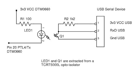
Это было протестировано с кучей различных дешевых серийных адаптеров USB и работал без каких -либо проблем. Если ваши серийные устройства USB составляют 5 В или 12 В, вам нужно будет повторно рассказать значение R2. Оба R1 и R2, вероятно, могут быть увеличены в стоимости на 50% или более, без потери данных. Я тестировал только 2400 бит / с, так как это по умолчанию Baudrate DTM0660.
TCRT5000 был выбран, потому что он дешевый (десять за фунт), легко разделенный на два, так как это фактически светодиод, фотосвязано и пластиковый зажим, держащий их без какого-либо клея. Таблица данных легко доступна, чтобы обеспечить легкий выбор подходящих значений для резисторов.
Опт-изололация важна, так как мультиметр может быть подключен к опасным напряжениям или заземлен на другом уровне, чем ПК. Без оптоизоляции существует значительный удар и риск волшебного дыма.
ПРИМЕЧАНИЕ. Поскольку оба устройства составляют 3V3, одна и та же схема будет работать, если подключиться к STM32 или ESP8226 или на любой другой микроконтроллер 3V3.
Две такие схемы позволили бы двунаправлено, изолированный поток данных между двумя микроконтроллерами, например, при работе с сетевым напряжением.
Zoomx
Чт 18 августа 2016 г. 9:51 утра
Изображения снова потеряны. 
Ахулл
Чт 18 августа 2016 г., 19:47
Zoomx написал:Изображения снова потеряны.
Martinayotte
Чт 18 августа 2016 г., 21:30
Изображения не работают ...
Может быть, в длинном 3 -километровом URL есть часть его, посвященная вашему сеансу, который вам нужно отказаться, так как мы, как зрители, никогда не вошли в вашу учетную запись, это предотвращает их отображение.
Может быть, в длинном 3 -километровом URL есть часть его, посвященная вашему сеансу, который вам нужно отказаться, так как мы, как зрители, никогда не вошли в вашу учетную запись, это предотвращает их отображение.
Ахулл
Чт 18 августа 2016 г., 22:04
Может, я должен найти мне лучший магазин изображений, чем Google..
Несмотря на то, что изображение было разделено, и в общем альбоме, и предположительно читаемой мировой.
Когда я специально делюсь индивидуальным изображением в своем собственном публичном сообщении Google+... Я получаю этот URL (более управляемый 9 см, а не 3 1/2 км)...
Вы можете увидеть, что это сейчас сейчас?
Martinayotte
Пт 19 августа 2016 г., 2:49
Этот показывает без проблем ...