Стивестронг
Вторник 22 мая 2018 г. 20:59
Привет, ребята,
Мне нужно инвертировать логический уровень входного цифрового сигнала с синей таблеткой (я хочу избежать использования внешнего оборудования для этого).
Единственное ограничение состоит в том, что выходной сигнал не должен быть задержан более чем до 200 нс по сравнению с входом.
Это ограничение уже исключает инвертирование в ISR attraintrupt (), который я пробовал, и которое занимает ~ 1 мкс.
Любые другие идеи?
Кто -нибудь уже сделал что -то подобное и имеет опыт и/или пример кода?
Я думаю, что это должно быть выполнимо с таймером, но я подумал, что лучше спрашиваю, прежде чем я начну делать некоторые испытания.
Ахулл
Вторник 22 мая 2018 г., 21:14
Я думал, что пойду на очевидное...
http: // www.LearningAboutelectronics.компонент ... Ircuit.PHP
Выполнять это быстро в программном обеспечении, однако без использования ISR .. хммм, позволь мне подумать об этом.
http: // www.LearningAboutelectronics.компонент ... Ircuit.PHP
Выполнять это быстро в программном обеспечении, однако без использования ISR .. хммм, позволь мне подумать об этом.
Эдогальдо
Вторник 22 мая 2018 г. 11:47
Думая о решении SW, я не думаю, что есть что -то быстрее, чем обработчик IRQ в любом случае.
Вы можете попытаться переопределить обработчик IRQ:
Вы можете попытаться переопределить обработчик IRQ:
  // Experimental current draw results typical values with power and/or blink LEDs lit.
//  subtract approx 4mA for the LED, 2mA for the regulator, and say 1mA for the resistance of the leads. .
// The halted CPU should be drawing <300uA With the processor halted, the meter was reading 7.9mA, so allowing for the quality of the meter, and other environmental issues.
// the results below look pretty accurate.. to within 1mA. Close enough for government work :¬)

// These look similar to the ST datasheet http://www.st.com/web/en/resource/technical/document/datasheet/CD00161566.pdf
// (Page 42 & 43)

// External (RCC_CLKSRC_HSE) 8MHz, no multiplier.
//  rcc_switch_sysclk(RCC_CLKSRC_HSE);                             // 8MHz => 16mA    -- datasheet value @20 deg. C  => between 5.5 and 6mA

// Internal (RCC_CLKSRC_HSI) 8MHz x RCC_PLLMUL_x multiplier.
// rcc_clk_init(RCC_CLKSRC_HSI, RCC_PLLSRC_HSE , RCC_PLLMUL_2);   // 16MHz  => 21 mA  -- datasheet value           => between 10 and 11mA

// Default configuration 72MHz
// rcc_clk_init(RCC_CLKSRC_HSI, RCC_PLLSRC_HSE , RCC_PLLMUL_9);   // 72MHz  => 48 mA  -- datasheet value           => between 40 and 41mA

// rcc_clk_init(RCC_CLKSRC_HSI, RCC_PLLSRC_HSE , RCC_PLLMUL_16);  // 128MHz => 69 mA  -- no data.
Rogerclark
Ср 23 мая 2018 г. 12:41
Если бы STM32 больше ничего не делал, то это сделает жесткая цифровая петля и DigitalWrite, но я предполагаю, что STM32 уже делает другие вещи
Интересно, можно ли как -то использовать таймер для этого и использовать систему OnePulse, используя внешний триггер ?
Интересно, можно ли как -то использовать таймер для этого и использовать систему OnePulse, используя внешний триггер ?
Стивестронг
Ср 23 мая 2018 г. 8:23
Я не могу проверить это в основном цикле, потому что Systick может вызвать более длительную задержку при обнаружении края.
Я постараюсь взломать один из __irq_extix isrs в Libmaple и проверить задержку в этом случае.
В противном случае я должен проанализировать возможность, используя таймер.
Я постараюсь взломать один из __irq_extix isrs в Libmaple и проверить задержку в этом случае.
В противном случае я должен проанализировать возможность, используя таймер.
Rogerclark
Ср 23 мая 2018 г., 9:19
Или отключить Systick, находясь в этой цикле
Эдогальдо
Ср 23 мая 2018 г., 11:02
Использование выгипа с более высоким приоритетом, чем Systick, будет предоставить 2 преимущества:
- Держите Systick доступным
- Возможность использовать основную петлю для других вещей
Стивестронг
Ср 23 мая 2018 г., 11:13
Где установлены приоритеты?
Я хочу сохранить систер.
И я хочу сохранить сериал USB.
Я хочу сохранить систер.
И я хочу сохранить сериал USB.
Эдогальдо
Ср 23 мая 2018 г., 11:25
Я думаю, что вы должны использовать nvic_irq_set_priority () из libmaple/nvic.час
Стивестронг
Чт 24 мая 2018 г., 18:21
Я взломал прерывание Exti, установил Flash Wait состояется до 1, но я мог получить только минимум 700NS времени реакции.
И я думаю, что это не будет меньше с IRQ.
Поэтому я вижу себя вынужденным изучать возможности, предлагаемые таймерами.
И я думаю, что это не будет меньше с IRQ.
Поэтому я вижу себя вынужденным изучать возможности, предлагаемые таймерами.
Эдогальдо
Чт 24 мая 2018 г., 19:27
Можете ли вы опубликовать свой код взлома прерывания?
В любом случае держите нас в курсе вашего прогресса, мне любопытно!
В любом случае держите нас в курсе вашего прогресса, мне любопытно!
victor_pv
Чт 24 мая 2018 г., 21:36
Стив, я считаю, что вы можете сделать это с таймером, но не совсем уверен (вы можете получить частоту сигнала, разделенную на два)
Установите таймер для внешнего ввода. Я полагаю, что таймер может быть настроен на оба края (но это, где я могу ошибаться, если учесть только один край, вы получаете A /2)
Установить переполнение до 1.
Установите канал N, чтобы провалить на каждом совместном соответствии, и установите сравнение на 1.
Каждый раз, когда уровень изменений входного сигнала будет увеличивать счетчик в реестре счетчиков, будет соответствовать регистрации сравнения, и канал будет перевернуть уровень.
Теперь, все это сказано, я бы пошел на аппаратное решение, как предложил Энди.
Стивестронг
Чт 24 мая 2018 г., 22:00
Да, я установил таймер 2 на внешний режим 1 (или 2), противостоять 0, захватить до 1, переполнить до 100.
На каждом входном часе генерируется IRQ, где я хочу изменить полярность ввода, чтобы получить новый IRQ в измененной полярности.
Теперь проблема в том, что таймер продолжает считать до переполнения, несмотря на то, что я останавливаю таймер и сбросил счетчик.
Хм.
На каждом входном часе генерируется IRQ, где я хочу изменить полярность ввода, чтобы получить новый IRQ в измененной полярности.
Теперь проблема в том, что таймер продолжает считать до переполнения, несмотря на то, что я останавливаю таймер и сбросил счетчик.
Хм.
Эдогальдо
Чт 24 мая 2018 г., 22:54
+1 для решения HW.
Если вместо этого вы хотите продолжать решение SW и не повезло с таймером, я бы посоветовал попробовать это:
Если вместо этого вы хотите продолжать решение SW и не повезло с таймером, я бы посоветовал попробовать это:
- Свяжите свой вход с 2 контактами, используя различные Exti IRQ (i.эн. PB2 и PB3)
- Определите свой выходной PIN (я.эн. PB4)
- Настройка 2 разных extis для роста против падения
//
// Example of RTC alarm triggering and changing clocks on the fly
//
//

#define BOARD_LED_PIN PB0
//#define BOARD_LED_PIN PC13

// Strictly speaking only the RTC crystal is necessary for this code to work.
#define BOARD_HAS_WORKING_RTC_CRYSTAL true
#define BOARD_HAS_WORKING_RTC_BATTERY true

// Define the Base address of the RTC registers (battery backed up CMOS Ram), so we can use them for config of touch screen or whatever.
// See http://stm32duino.com/viewtopic.php?f=15&t=132&hilit=rtc&start=40 for a more details about the RTC NVRam
// 10x 16 bit registers are available on the STM32F103CXXX more on the higher density device.
#define BKP_REG_BASE   (uint32_t *)(0x40006C00 +0x04)

// Defined for power and sleep functions pwr.h and scb.h
#include
#include

// These are possibly defined somewhere but I couldn't find them.
// System Control Register Bits. See...
// http://infocenter.arm.com/help/index.jsp?topic=/com.arm.doc.dui0497a/Cihhjgdh.html
#define SCB_SCR_SLEEPDEEP 4       // This register bit controls deepsleep(1) or sleep(0)
#define SCB_SCR_SLEEPONEXIT 2     // This register bit controls sleeponexit. i.e. do we go back to sleep immediately after serviceing the interrupt, or go back to the main loop.
#define SCB_SCR_SEVONPEND 16      // Controls Send Event on Pending bit:

// Set up RTC and choose one of the available clocks.
// The HSE/128 works in all boards
// Boards with a 32kHz RTC crystal fitted can choose any clock (but I suggest using LSE as this is the 32kHz clock).
//
#include "RTClock.h"
uint32 tt;

#ifdef BOARD_HAS_WORKING_RTC_CRYSTAL true
RTClock rt(RTCSEL_LSE);
#else
RTClock rt(RTCSEL_HSE);
// Alternatives...
// RTClock rt(RTCSEL_LSI);
// RTClock rt; // this starts HSE clock as a default.
#endif

// Time library - https://github.com/PaulStoffregen/Time
#include "Time.h"

// Somewhere to store the current time.
int thisYear = 2015;
int thisMonth = 6;
int thisDay = 27;
int lastDay = 0;
int thisHour = 0;
int thisMinute = 0;
int thisSecond = 0;

// Since some of these are used in the ISRs, they probably need to be volatile.
bool ledOff = true;
bool alarmTriggeredFlag = false;
bool secInterruptFlag = false;
bool deepSleepFlag = false;

long int globSecCnt = 0;    // Number of secondsInterrupts this session.
// NOTE: globSecCnt is *not* preserved in deepsleep as the system restarts (ram contents are lost) after deepsleep.
// The RTC of course does keep an accurate count of seconds.
// Caveat, RTC time, and the RTC battery backed registers are preserved in deepsleep only if there is a voltage source (generally a battery) connected to vBat.
// Some boards have vBat connected to VDD,the main STM32FXX 3V3 power supply so their RTC will keep working so long as the main power is preserved.
// Flash is always preserved in deepsleeep, so writing to flash would be the best way to preserve config in excess of the
// 14 bytes offered by the RTC when in deepsleep.

long int alarmDelay = 5;   // Seconds between restarts if using deepsleep, or time of first alarm if using sleep (subsequent sleeps can be set in the loop() section.

struct tm time_tm, *tm_ptr; // This is a structure with date and time fields, used to set the time if BOARD_HAS_WORKING_RTC_CRYSTAL is false.

int numFlashes = 1;
int loopCounter = 0;


// Create USB serial_debug port
USBSerial serial_debug;


void setup() {


// This may be needed if we find the sys clock is incorrect after wakeup
// Set up clock, PLL an multiplier
// Chose RCC_PLLMUL_9 and RCC_PRESCALER_USB, 1.5 for 72MHz fom 8MHz crystal (standard STM32F103 speeds on most clone boards).
// Chose RCC_PLLMUL_6 and RCC_PRESCALER_USB, 1 for 48MHz lower power from 8MHz crystal (standard STM32F103 speeds on most clone boards)
// rcc_clk_init(rcc_sysclk_src sysclk_src, rcc_pllsrc pll_src, rcc_pll_multiplier pll_mul)
// rcc_clk_init(RCC_CLKSRC_HSI, RCC_PLLSRC_HSE , RCC_PLLMUL_9);
// rcc_switch_sysclk(rcc_sysclk_src sysclk_src)

// DANGER - here be dragons.
// Switch to external 8MHz clock, set multipler, switch back to internal
// rcc_switch_sysclk(RCC_CLKSRC_HSE);
// rcc_clk_init(RCC_CLKSRC_HSI, RCC_PLLSRC_HSE , RCC_PLLMUL_2);
// rcc_clk_init(RCC_CLKSRC_HSI, RCC_PLLSRC_HSE , RCC_PLLMUL_16);
// rcc_switch_sysclk(RCC_CLKSRC_HSI);
//
// rcc_clk_init(RCC_CLKSRC_HSE, RCC_PLLSRC_HSE , RCC_PLLMUL_16);
// rcc_switch_sysclk(RCC_CLKSRC_HSE);


// Likewise for the USB prescaler
// rcc_set_prescaler(rcc_prescaler prescaler, uint32 divider)
// rcc_set_prescaler(RCC_PRESCALER_USB, 1);
// or
// rcc_set_prescaler(RCC_PRESCALER_USB, 1.5);

pinMode(BOARD_LED_PIN, OUTPUT);//setup our alive pin.
digitalWrite(BOARD_LED_PIN, ledOff);


// If we have a working RTC crystal, we do nothing, this will simply preserve the current time, otherwise with no working RTC crystam we set something sane in the RTC instead.
if (!BOARD_HAS_WORKING_RTC_CRYSTAL)
{
setSaneRTC();
}


delay(3000);
serial_debug.println(".");
serial_debug.println(".");
serial_debug.println(".");
showTime();
serial_debug.println("I'm back! ... 72 MHz, and I either just powered on, or woke from deepsleep.");
// Mess with the SYSCLK

for ( int runs = 1; runs < 3; runs++)
{
int flashesPerRun = 3;
// Attempt to set up 48MHz and 1x USB clock
clockARM48();

numFlashes = 1;
for ( int x = 0; x < flashesPerRun; x++ )
{
serial_debug.println("LED Flash @48MHz!");
flashLED(numFlashes);
}

// Back to 72MHz and 1.5x USB clock
clockARM72();

numFlashes = 1;
for ( int x = 0; x < flashesPerRun; x++ )
{
serial_debug.println("LED Flash @72MHz!");
flashLED(numFlashes);
}
}

// If not using deepsleep, you can enable the secondsInterrupt ISR, and wakeup every second. This is less energy efficent obviously.
// FIXME: It has an effect on deepsleep in this sketch, so can not be left configured.
// rt.attachSecondsInterrupt(&serviceSecondsInterrupt);  //Set the SecondsInterrupt  ISR to fire (every second obviously).

// Set the inital alarm timer to wakeup now + alarmDelay seconds
setNextAlarm();
showAlarmDelay();
serial_debug.println("Completed setup(); Alarm trigger set");
showTime();
delay(1000);
}

void loop() {
loopCounter++;
showTime();
serial_debug.println("Started loop() - Setting clock to 72MHz");
clockARM72();
// Set loop alarm delay (seconds).
alarmDelay = 5*loopCounter;
showAlarmDelay();
tt = rt.getTime();

//Note: If we use deepsleep, the rest of this code will do nothing since we never actually get the alarmTriggeredFlag set.
// The perhaps less than obvious reason for this is that deepsleep restarts the CPU on wakeup, so the flag is cleared.

// Check Alarm triggered flag
if (alarmTriggeredFlag)
{
alarmTriggeredFlag = false;
// 3 flashes.. we came back from low power mode without restarting.
// clockARM48()
serial_debug.println("alarmTriggeredFlag was set by the ISR while we were doing other stuff. Sending 3 Blinks of the LED * * *");
numFlashes = 3;
flashLED(numFlashes);
//delay(2000);

//Ready ourselves for another alarm in N seconds
// alarmDelay = 10;
setNextAlarm();
showAlarmDelay();
} else {
// 8 quick flashes to prove we got here, either at power on or deepsleep power on.
// clockARM48();
if (secInterruptFlag)
{
serial_debug.println("We are in loop(); Alarm not triggered, you should see the LED flashing due to the secondsInterrupt ISR");
} else {
serial_debug.println("");
}
}

// Check seconds interrupt flag
if (secInterruptFlag)
{
// We dont have much time here.. the next interrup is due in 1 second
// Do *something* to prove we were here.
serial_debug.println("secInterruptFlag cleared");
secInterruptFlag = false;

}

//serial_debug.println("Setting clock to 8MHz HSI");
//clockARM8();
//delay(1000);

// Sleep mode - save some power while we wait for the next alarm.
// if deepSleepFlag=true we deepsleep, otherwise, we just sleep

if (loopCounter % 5 == 0 )
{
deepSleepFlag = true;
} else {
deepSleepFlag = false;
}

showTime();
if (deepSleepFlag)
{
serial_debug.println("Attempting to deepsleep");
delay(1000);
sleepMode(deepSleepFlag);
} else {
serial_debug.println("Attempting to slow to 48 MHz - the next delay() will be much longer than normal");
clockARM48();
serial_debug.println("Starting delay(1000);");
delay(1000);
clockARM72();
serial_debug.println("Back to 72MHz");
}

//sleepMode(deepSleepFlag);
delay(1000);
}

void serviceSecondsInterrupt()
{
if (rtc_is_second())
{
//toggleLED();
globSecCnt++;
secInterruptFlag = true;
//toggleLED();
}
}

void AlarmFunction () {
alarmTriggeredFlag = true;
return;
}


void toggleLED ()
{
ledOff = !ledOff;
digitalWrite(BOARD_LED_PIN, ledOff);
}


// Set a relatively sane RTC time to work from if there is no battery or RTC crystal fitted.
void setSaneRTC()
{
// Set the RTC time to 12:45:00 18th Oct 2015 using a tm struct.
//    see http://www.cplusplus.com/reference/ctime/tm/

time_tm.tm_hour = 12;
time_tm.tm_min = 45;
time_tm.tm_sec = 0;

time_tm.tm_mday =  18;
time_tm.tm_mon = 10;
time_tm.tm_year = 115;//  Per standard C "struct tm" ... years since 1900

rt.setTime(&time_tm);

}

// Quick (N times) flashes on the LED
// Timing will be in mS *only* if the processor clock is running at the correct rate.
void flashLED(int numFlashes)
{
int flashLen = 80; //mS ?
ledOff = true;
if (numFlashes > 0)
{
for (int i = 0 ; i < numFlashes; i++ )
{
for (int j = 0; j < 2; j++)
{
toggleLED();
delay(flashLen);
}
}
}
}


void sleepMode(bool deepSleepFlag)
{
// Clear PDDS and LPDS bits
PWR_BASE->CR &= PWR_CR_LPDS | PWR_CR_PDDS | PWR_CR_CWUF;

// Set PDDS and LPDS bits for standby mode, and set Clear WUF flag (required per datasheet):
PWR_BASE->CR |= PWR_CR_CWUF;
PWR_BASE->CR |= PWR_CR_PDDS;
// Enable wakeup pin bit.
PWR_BASE->CR |=  PWR_CSR_EWUP;


// Low-power deepsleep bit.
// PWR_BASE->CR |= PWR_CR_LPDS;

// System Control Register Bits. See...
// http://infocenter.arm.com/help/index.jsp?topic=/com.arm.doc.dui0497a/Cihhjgdh.html
if (deepSleepFlag)
{ // Experimental
// Set Power down deepsleep bit.
PWR_BASE->CR |= PWR_CR_PDDS;
// Unset Low-power deepsleep.
PWR_BASE->CR &= ~PWR_CR_LPDS;
// Set sleepdeep in the system control register - if set, we deepsleep and coldstart from RTC or pin interrupts.
SCB_BASE->SCR |= SCB_SCR_SLEEPDEEP;
} else {
//  Unset Power down deepsleep bit.
PWR_BASE->CR &= ~PWR_CR_PDDS;
// set Low-power deepsleep.
PWR_BASE->CR |= PWR_CR_LPDS;
/*
* PWR_CR_PDDS
Power down deepsleep.
PWR_CR_LPDS
Low-power deepsleep.
*/
// Unset sleepdeep in the system control register - if not set then we only sleep and can wake from RTC or pin interrupts.
SCB_BASE->SCR |= SCB_SCR_SLEEPDEEP;
// Low-power deepsleep bit.

}

// Set end Event on Pending bit: - enabled events and all interrupts, including disabled interrupts, can wakeup the processor.
// SCB_BASE->SCR |= SCB_SCR_SEVONPEND;

// Set SLEEPONEXIT -Indicates sleep-on-exit when returning from Handler mode to Thread mode -
// if enabled, we will effectively sleep from the end of  one interrupt till the start of the next.
// SCB_BASE->SCR |= SCB_SCR_SLEEPONEXIT;

// Now go into stop mode, wake up on interrupt
asm("    wfi");

}

void ledpulse()
{
toggleLED();
toggleLED();
}


void clockARM48()
{
// slow! div speed. NOTE! 512 is stop/hang when USB not connected!
//rcc_set_prescaler(RCC_PRESCALER_AHB, RCC_AHB_SYSCLK_DIV_256);

// Clock divisor Normal speed
rcc_set_prescaler(RCC_PRESCALER_AHB, RCC_AHB_SYSCLK_DIV_1);


// Attempt to set up 48MHz and 1x USB clock
rcc_switch_sysclk(RCC_CLKSRC_HSE);
rcc_set_prescaler(RCC_PRESCALER_USB, 1);
//rcc_clk_init(RCC_CLKSRC_HSI, RCC_PLLSRC_HSE , RCC_PLLMUL_6);
rcc_clk_init(RCC_CLKSRC_HSE, RCC_PLLSRC_HSE , RCC_PLLMUL_6);
rcc_switch_sysclk(RCC_CLKSRC_HSI);
//rcc_switch_sysclk(RCC_CLKSRC_PLL);
}

void clockARM72()
{

// Clock divisor Normal speed
rcc_set_prescaler(RCC_PRESCALER_AHB, RCC_AHB_SYSCLK_DIV_1);

// Attempt to set up 72MHz and 1x USB clock
rcc_switch_sysclk(RCC_CLKSRC_HSE);
rcc_set_prescaler(RCC_PRESCALER_USB, 1.5);
rcc_clk_init(RCC_CLKSRC_HSE, RCC_PLLSRC_HSE , RCC_PLLMUL_9);
// rcc_switch_sysclk(RCC_CLKSRC_HSI);
rcc_switch_sysclk(RCC_CLKSRC_PLL);
}

void clockARM8()
{

// Clock divisor slow speed
rcc_set_prescaler(RCC_PRESCALER_AHB, RCC_AHB_SYSCLK_DIV_256);

// Attempt to set up 72MHz and 1x USB clock
//rcc_switch_sysclk(RCC_CLKSRC_HSE);
//rcc_set_prescaler(RCC_PRESCALER_USB, 1.5);
//rcc_clk_init(RCC_CLKSRC_HSE, RCC_PLLSRC_HSE , RCC_PLLMUL_9);
// rcc_switch_sysclk(RCC_CLKSRC_HSI);
//rcc_switch_sysclk(RCC_CLKSRC_PLL);
}

void setNextAlarm()
{
// Set the alarm timer to wakeup now + alarmDelay seconds
time_t nextAlarm = (rt.getTime() + alarmDelay); // Calculate from time now.
rt.createAlarm(&AlarmFunction, nextAlarm);      // Set the alarm to trigger (alarmDelay) later...
}

void showAlarmDelay()
{
serial_debug.print("Alarm Delay set to ");
serial_debug.print(alarmDelay);
serial_debug.println(" seconds.");
}


void serialCurrentTime() {
serial_debug.print("# Current STM32 time - ");
if (hour(tt) < 10) {
serial_debug.print("0");
}
serial_debug.print(hour(tt));
serial_debug.print(":");
if (minute(tt) < 10) {
serial_debug.print("0");
}
serial_debug.print(minute(tt));
serial_debug.print(":");
if (second(tt) < 10) {
serial_debug.print("0");
}
serial_debug.print(second(tt));
serial_debug.print(" ");
serial_debug.print(day(tt));
serial_debug.print("/");
serial_debug.print(month(tt));
serial_debug.print("/");
serial_debug.print(year(tt));
//serial_debug.println("("TZ")");
}

void showTime()
{
tt = rt.getTime();
serialCurrentTime();
serial_debug.println();
}
Стивестронг
Пт 25 мая 2018 г., 7:04
@edogaldo, я попробовал Exti IRQ, но они занимают слишком много времени, даже переопределяются с моей оптимизированной рутиной и уменьшенным состоянием ожидания вспышки не может быть ниже 700 нс.
Никакой дополнительной внешней HW не является одним из требований.
Решение на таймер должно работать, просто мне нужно больше времени потратить на него 🤨
К счастью, между краями входного сигнала есть пара микросхемы, так что после генерации инвертированного сигнала есть время для ISR.
Никакой дополнительной внешней HW не является одним из требований.
Решение на таймер должно работать, просто мне нужно больше времени потратить на него 🤨
К счастью, между краями входного сигнала есть пара микросхемы, так что после генерации инвертированного сигнала есть время для ISR.
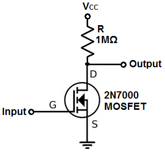
Пито
Пт 25 мая 2018 г. 16:01
2 комментария к вышеуказанной схеме с 2N7000..
а. лучше использовать MOSFET логического уровня, с VGT = 1.0-1.5 В
беременный. Всегда заземляйте ворота что -то вроде 10к (или меньше)..
а. лучше использовать MOSFET логического уровня, с VGT = 1.0-1.5 В
беременный. Всегда заземляйте ворота что -то вроде 10к (или меньше)..
Стивестронг
Сб 26 мая 2018 г., 9:19
В итоге я получил следующий код:
[454833.555038] usb 1-1.2: device descriptor read/64, error -32
[454833.731004] usb 1-1.2: device descriptor read/64, error -32
[454833.906980] usb 1-1.2: new low-speed USB device number 84 using ehci-pci
[454833.978967] usb 1-1.2: device descriptor read/64, error -32
[454834.154941] usb 1-1.2: device descriptor read/64, error -32
[454834.330917] usb 1-1.2: new low-speed USB device number 85 using ehci-pci
[454834.738853] usb 1-1.2: device not accepting address 85, error -32
[454834.810846] usb 1-1.2: new low-speed USB device number 86 using ehci-pci
[454835.218779] usb 1-1.2: device not accepting address 86, error -32
[454835.218899] usb 1-1-port2: unable to enumerate USB device